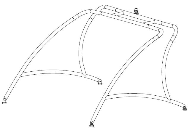
ORIGIN WAKEBOARD TOWER II
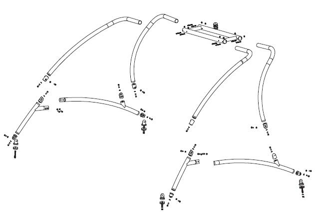
EXPLODED VIEW OF THE ORIGIN TOWER FOR YOUR REFERENCE
STEP 1:
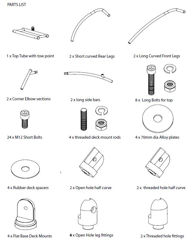
Unpack and check the contents of the box. Check the parts list and the Instruction Guide correspond
with the product you purchased. Ensure you have the correct tools to complete the Installation.
If you do not have the skills to complete the installation hire someone who can install for you.
Please Read all Instructions prior to starting installation.
If you are NOT sure of any part of the guide or you have any questions please contact us.
Email: jamesgbrands@gmail.com
PARTS LIST
Step 2: Assemble the side bars of the wakeboard tower.
Note there is a left and right side bars. You will also see that one end has a welded lap joint with two
holes for bolts to attach them together.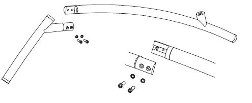
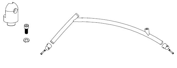
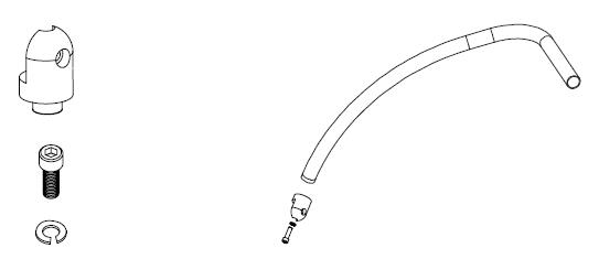
Step 3:
Attaching the end !ttings to the side bars. Insert the the raised circle base of the !tting into the
counter sunk are at the ends of the tubes. Use the short M12 bolt and split washer inserted through the
centre of the !tting into the threaded hole. Note the shape of the end !ttinghas a open hole from the
side.
(a) Note only attach to the bottom of the side are that attaches to the deck mounts.
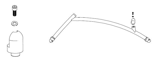
 Step 4: Attaching threded !tting to the side bar.
Note The !tting has a threded hole in the "at face of the !tting. Insert the raised circle base of the !tting
into the counter sunk area welded onto the curved side bar towards the back - see picture below.
Use the short M12 bolt and split washer inserted through the centre of the !tting into the threaded hole.
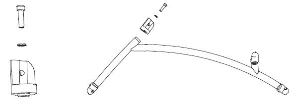
 Step 4.1: Attaching !tting to the vertical section of the side bars.
Note the !tting has a half circle shape at one end. Insert the raised circle base of the !tting into the
counter sunk area of the vertical bar section of the side bar. - see picture below. Use the short M12 bolt
and split washer inserted through the centre of the !tting into the threaded hole.
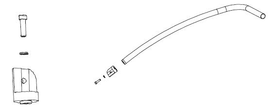
 Step 4.2: Attaching end !tting to the front legs.
Note the !tting has a half circle shape at one end. Insert the raised circle base of the !tting into the
counter sunk area at the end of the front leg. - see picture below. Use the short M12 bolt
and split washer inserted through the centre of the !tting into the threaded hole.
 Step 5: Attaching the end !ttings short curved rear legs. Insert the the raised circle base of the !tting
into the counter sunk are at the end of the leg. Use the short M12 bolt and split washer inserted through
the centre of the !tting into the threaded hole. Note the shape of the end !tting has a open hole from
the side.
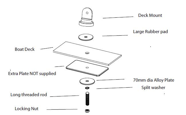
 Step 5.1: Assembly of Deck Mount Reference
Note the shape and the "at base of the deck mount.
Note the threaded hole from the bottom of the base of deck mount.
 Step 6: Installation of Front Deck Mounts onto Boat .
Distance between Front Mounts centre to centre across the boat 190 to 250 cm wide.
There is a bit of tolerance where you can cut down if needed.
Recommended guide place on the side of the deck. We recoomend to Use extra plate of (ply or Alloy)
underneath the deck between the our alloy plate and the hull of the boat. (see picture above)
WARNING: Check that you have clear access to the area for drilling and tightening bolts.
Check for objects, wires or other hazards you could damage when drilling.
Do not measure from or use windscreens, cleats, vents as a reference point. These objects are
not always square and the same as the opposite side. It is best to use the front of the boat as the reference
point and also the top edge of the deck mould or similar if possible.
Always triple measure and check before drilling.
Tighten the deck mounts !rm but not locked into position as you will still need to rotate and align at a later
point during installation.
Step 7: Installing the side bars !rst.
There is a left and right side bar. There is a slight inwards curve on the vertical section at the front.
(a) Attach the deck mounts to the ends of the side bars. You should be able to slightly rotate the deck
mounts to face the boat.
INSTALLATION GUIDE - ORIGIN TOWER OWT-1
www.origintower.com.au
This is approx - you can move forwards or backwards to suit
windscreen
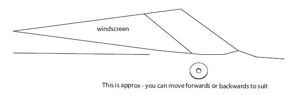
(b) Have a friend hold the side bar with the deck mounts against the boat. Please be careful not to
scratch your boat. You can move the side bar forwards and backwards to where it looks the best to
suit your boat. The picture above give you a starting point for the front mount position.
(c) Once you have market the the front and rear areas. Check under the deck to make sure you have
clear access to drill and tighten the mounts. Measure the location of the front mount and check the
the other side for easy access and no objects in the way.
(d) If all is clear drill only the front deck mount holes. Install the deck mounts and then attach the side
bar. Once you have the side bar attached at the front you can then get the exact location of the rear hole.
Attach the rear deck mount and side bar.
Now you tigthen the deck mounts from the inside of the boat in the !rm locked position.
(e) The side bars can be tighten in the vertical position, do not rely on measuring from the windscreen
as these are not always square with the boat. Also you boat might not be square on your trailer. You will
have to do this by eye at the moment.
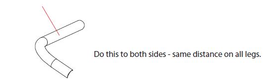
Step 8: Mark all the legs with a reference point towards the elbow bend.
 Step 8.1: Attaching the front legs to the side bars.
NOTE: during this process you should NOT be forcing anything.
(a) Attach a rear leg to the side bar, check that the !tting will allow you to pivot the rear legs backwards.
Lay the rear leg down the the back of the boar.
(b) The top H section can now be inserted over the rear leg into the tube. Ensure that you do not
scratch the leg and make sure the tow point is to the rear. Face the H Section in a vertical postion.
(c) Now you can insert the other rear leg into the top H section and attach to the side
bar !tting.
Take the H Section to the rear legs. Now you can check that the tower can pivot on the rear legs
correct. Raise and lower the top section pivoting the rear legs. Make sure you have backed of the bolts
in the rear leg !ttings. The tower should move freely. If jaming check that you have side bars vertical and
the face of the !ttings are vertical and square with the boat at the bottom of the rear legs. Once moving
correct tighten and mark these joints.
(d) Now you can insert the front legs into the H section and lift the tower into position and attach the
front legs to the side bars.
(e) Now you can centre the tow point, using the reference marks you made on the legs.
Step 9: Adjustments to the tower and !ttings.
(a) Do a visual look from the side and front to see how the tower is sitting on you boat.
You may need to push the side bars in or out. You may need to also adjust the telescopic top with moving
the legs in or out.
(b) Now you can centre the tow ball look at it from the front at rear. You can also take measurements from
the edge of the H section tube to the mark you make early on the legs to check how it is sitting.
(c) Now you can drill and bolt the top section. Check that you can lower the tower freely at the joints before
drilling. (read below also)
Step 9.1: Checking the !ttings and folding the tower.
At all the !tting you can make a mark across the joint as a reference point.
(a) Remove the boats from the front legs where it attaches to the side bars. loosen the rear bolts on the
rear legs attaching to the side bar. Now you can lay the tower back wards. DO NOT FORCE THE TOWER
if the !ttings jam. You will have to loosen and adjust the !ttings to be square to they can move freely.
Adjust !rst and lock and check this otherwise you will strip the threads of the !ttings.
(b) The front legs will come down "at by removing the small bolt from the top of the H section.
Step 9.2: Attaching the front legs to the side bars.
NOTE: during this process you should NOT be forcing anything.
(a) Attach the front leg to the side bar, check that the !tting will allow you to pivot the front legs.
Attach one leg to the side bar and lay down on the boat.
(b) The top H section can now be inserted over the front leg into the tube. Ensure that you do not
scratch the leg and make sure the tow point is to the rear.
(c) Now you can insert the other front leg into the top H section and attach it to the front of the side
bar !tting.
You will need a couple of people to help you now.
(d) Have one person lift the H section and front legs so they are inline with the side bar. tigthen the
front join between the legs and the side bar.
(e) Now slide one of the rear legs into the top section, ensure that you do not scrath the leg. Attach
it to the rear mount on the side bars. You will have to rotate the !ttings so they come together nice
and easy. tigthen this joint.
(f) Now repeat with the other rear leg on the opposite side.
(g) Now tape up the Top H section in place.
Step 9.3: Adjustments to the tower and !ttings.
(a) Do a visual look from the side and front to see how the tower is sitting on you boat.
You may need to push the side bars in or out. You may need to also adjust the telescopic top with moving
the legs in or out.
(b) Now you can centre the tow ball look at it from the front at rear. You can also take measurements from
the edge of the H section tube to the mark you make early on the legs to check how it is sitting.
(c) Now you can drill and bolt the top section.
Step 9.4: Checking the !ttings and folding the tower.
At all the !ttings make a mark across the joint as a reference point.
(a) Remove the bolts from the front legs where it attaches to the side bars. loosen the rear bolts on the
rear legs attaching to the side bar. Now you can lay the tower back wards. DO NOT FORCE THE TOWER
if the !ttings jam. You will have to loosen and adjust the !ttings to be square to they can move freely.
Adjust !rst and lock and check this otherwise you will strip the threads of the !ttings.
(b) The front legs will come down "at by removing the small bolt from the top of the H section.
LOCK TIGHT BOLTS AND FITTINGS.
When you are happy with lowering of the tower. Use the reference marks across the !ttings, remove the !tting
one by one and use lock tight on all the bolts. Do NOT lock tight the bolts you need to loosen to fold the tower.
NOTE: Use lanilon or similar clear spray to protect bolts from the environment.
CARE AND MAINTENANCE
Check and tighten all fastners and connections prior to every use Be cautious when towing or driving under
obstacles, low hanging structures or trees. Leave tower in the erect position when towing behind a vehicle
Use soap and water to clean your tower. Always rinse and wipe down tower after contact with salt (brackish)
water. You will have to keep this tower polished to keep its nice shine. If Powder coated tower wipe and keep
clean do not use abrasive materials or liquids to clean. Check before using cleaning agents on tower.
WARRANTY
Origin warrants the product (not including other 3rd party accessories) against manufactures defects for
5 years to the Original purchaser/owner.
To claim you must contact Origin at email: jamesgbrands@gmail.com
The product/part maybe requested is to be sent to Origin for inspection where it will either be
repaired or replaced. (unless otherwise agreed in writing)
The customer is liable for costs associated in shipping the product/part to Origin Distributor.
Origin (James G Pty Ltd) is not responsible for personal injury or damage to the boat caused by the use of t
he tower or any transport charges or cost of installation or removal of the tower. Origin is not liable for direct
or indirect or consequential damages resulting from delay or improper installation.
Warranty does not cover anodised, polished and powder coated surfaces as well as any hardware
corrosion. They are speci!cally excluded as their care and use can not be controlled by Origin.
Warranty does not cover the spider coat gel cracking or damage from the installation or use of
the tower on your boat. No dealer, retailer or manufacturer is the agent of James G Pty Ltd and may
not assume any liablity in connection with this warranty. This warranty is in lieu of all.
WARNING
The construction of your boat, design of the deck, thickness of deck and walls and overall design may
cause movement at the mounting points.
If the construction of you boat causes movement at the mounting points or incorrect mounting location
creates added pressure on joints increasing movement of the tower it voids warranty if there is a fault.
If in doubt do not install the tower. Check all bolts and parts prior to use, especially after towing behind a
vehicle, lowering and raising after storage.
WARNING
Do not stand, climb or jump o" tower, do not tow a boat behind a vehicle with the tower lowered.
Do Not Ski, tow tubes, boats or other watercraft from the tower. Watch out whilst moving under
objects, such as bridges, low building and trees.
 Call 0 414 678978
 Pay as you wish via PayPal or credit card.